MIL-DTL-22200/1H(SH)
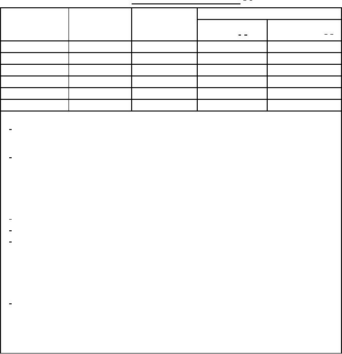
TABLE XIII. MIL-11018-M welding requirements. 1/
2/
Welding parameters
Minimum
Maximum root
Electrode size
thickness (T)
opening (R)
Heat input
Preheat/interpass
(inches)
temperature (°F) 5/ 6/
(inches)
(inches)
(KJ/in) 3/ 4/
3
¾
½
30-35
200-225
/32
¾
½
35-41
200-225
5
¾
½
45-51
200-225
/32
3
¾
½
51-57
200-225
/16
7
1
½
51-57
200-225
/32
¼
1
½
51-57
200-225
NOTES:
1/
Pass and layer sequence shall be reported. A sketch is acceptable, as is use of written format for bead
placement, such as 1 full, 2 split, 3 triple, and 5 quad layers. The final weld layers shall include a
reinforcement of standard proportions (1/32 inch to inch).
2/
Welded test assemblies shall be insulated or separated from the workbench. To minimize the angular
distortion of the completed test weld, test assemblies shall be fully restrained during heating, welding and
cooling by appropriate fixturing, unless otherwise specified (see 6.2). Restraining fixtures shall not interfere
with the placement of strip heaters or heating pads on the backside of the assembly. Contact points between
the fixture and the test plates shall be minimized to minimize the heat sink effect of the fixturing. Base
plates either side of the weld joint shall not be back set (reverse distorted) before welding to compensate for
weld shrinkage, as an alternative to the required fixturing.
3/
Alternate NAVSEA approved heat inputs and test plate thickness may be specified (see 6.2).
4/
See 4.6.2.2 for heat input calculation procedures.
5/
Preheat shall be applied evenly along the length of the plate using electric resistance contact strip heaters or
electric resistance ceramic pad heaters. If temperature indicating crayons are used, the preheat and interpass
temperature shall be measured at several points along the entire length of weld 1 to 1½ inches from the edge
of the bevel on both plates being joined. If a contact pyrometer is used, the preheat and interpass
temperature shall be measured in at least 3 places 1 to 1½ inches from the bevel on each side of the plate (at
each end and the middle). The heat shall be applied in a way to ensure that it is through thickness, with the
heater strips or heater pads on the bottom of the plate (opposite from the side being welded).
6/
After completion of each pass, the interpass temperature of the assembly shall be checked and the assembly
shall be allowed to cool or shall be reheated, as required to maintain the assembly temperature in the preheat
range as specified in table XIII. Any required cooling of test assemblies shall be done in still air at room
temperature, and assemblies shall not be force cooled with compressed air or by any other means. If it is
necessary to interrupt this procedure, and the assembly cools, the assembly shall be reheated to the preheat
temperature, as specified in table XIII, prior to resuming welding.
19
For Parts Inquires call Parts Hangar, Inc (727) 493-0744
© Copyright 2015 Integrated Publishing, Inc.
A Service Disabled Veteran Owned Small Business